Welcome to our Community
Wanting to join the rest of our members? Feel free to sign up today.
Sign up

How to Disconnect Motor from Motherboard?

JClarkW

Member
Joined
Feb 4, 2019
Messages
7
Reaction score
5
Dirk_ANAFI posted valuable instructions (attached) for replacing the Mambo central cross at the following thread in the drone-forum:

Tools Needed? - drone-forum.com

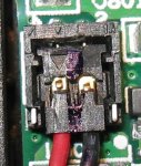
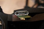
Basically one takes the Mambo almost completely apart, including specifically disconnecting the motor wires from the motherboard (stage 2, step 2, "Disconnect the motors' connectors"). There are tiny connectors that must be separated, but it's not clear how to accomplish this. Before I apply excessive force and damage something, can anyone tell me

1) Which direction the connector is supposed to move out of its socket?
2) Is there a spring clamp of some sort holding it, or just friction on contact pins?
3) Any tips on how to do this without damage?

Thanks in advance for any suggestions! -- JClarkW
 

Attachments

  • MAMBO_CENTRAL_CROSS_EN.pdf
    2 MB · Views: 7
I never did it with Mambo.
But mostly those connectors move out of their sockets in the direction of the cables.
So carefully pulling at the cables with a bit moving left/right will do the job.
 
I never did it with Mambo.
But mostly those connectors move out of their sockets in the direction of the cables.
So carefully pulling at the cables with a bit moving left/right will do the job.

This cannot be right -- see highly magnified photo attached.

It appears that the connector cannot slide horizontally out of its socket in the direction of the wires (or any other direction), since the socket forms a cage 3/4 around it with keyways that should prevent motion in the wire direction.

Note also the metal pieces on the corners of the socket next to the wires. These look like some sort of spring clamps, but I could be wrong...

I guess the connector must come out vertically (as in fact suggested by the image in the instructions you sent), but so far I haven't gotten it to budge by wiggling and pulling on the wires, attempting to insert a very fine flat-blade screwdriver under it, or anything else.

Anybody ever done this??? -- JClarkW
 

Attachments

  • 20190205-IMG_1750.jpg
    20190205-IMG_1750.jpg
    186 KB · Views: 10
...I guess the connector must come out vertically (as in fact suggested by the image in the instructions you sent)...

I just found a YouTube video for this type of repair on the Rolling Spider, which looks very similar (I'm not succeeding in inserting the link here). Although there is no commentary, just silly music, it appears the tech is simply lifting up on the wires to snap the connector out of its socket. I had already tried this without success but will try again... -- JClarkW
 
Hard to tell from the picture but if I had to guess the two brass looking fittings almost look like the antenna connectors they use which would just pop up and off. Not having it in front of me thats the best I can tell you.
Good luck
 
  • Like
Reactions: JClarkW
Hard to tell from the picture but... the antenna connectors they use which would just pop up and off..
Good luck

Yep, that's the way it worked. Lift the wires smartly, and the connector pops up. To re-install, fit the end opposite the wires into the socket and the press on the wire end with a finger until it snaps down. -- JClarkW
 
Dirk_ANAFI posted valuable instructions (attached) for replacing the Mambo central cross...

On to the next problem: In the same instructions, stage 5, step 3, "Press on the motor to secure it in the foot of the Parrot Mambo," the fit is extremely tight. I can see that the phenolic board on the bottom of each motor is keyed to fit into slots in these feet (presumably to prevent rotation), but it's not clear how to get the motors in to full depth without breaking something.

To get the motors out of the "feet" of the old cross (stage 2 step 5) was hard enough -- I had to place a screw driver in contact with the base of each motor and then tap on the screwdriver handle with a hammer in order to work it out!

It's not clear how to reverse this procedure without damaging the shaft of the motor and/or splitting the foot of the cross (my original problem). Any suggestions would be most welcome! -- JClarkW
I also never did that.
But I would try to heat the motor base either carefully with a hairdryer or in warm water (40..60 °C) for a few minutes,- then quickly pushing in the motor.
 
  • Like
Reactions: JClarkW
...I would try to heat the motor base ...in warm water (40..60 °C) for a few minutes,- then quickly pushing in the motor.

"Good thinking, Robin!" This actually worked fairly well, although I had to repeat it on one motor to get it fully inserted. Thanks! -- JClarkW
 
  • Like
Reactions: Dirk_ANAFI
On to the next problem...

The final insult: In Stage 4, steps 2&3, the "plastic cover" and "top part of the motherboard" don't fit into the new central cross. The rear strut on the old central cross (where the USB connector comes through) was straight across, whereas the new one is angled inward so that it interferes with both parts. (Perhaps there was a motherboard change between my original Mambo FPV and the replacement central cross?) I had to trim down the rear end of the cover so it would fit and also cut away part of the new strut to make room for the USB connector and part of the end of the motherboard (see somewhat sloppy job in the attached photo). The good news is that the central cross material cuts fairly easily with a razor blade.

Anyhow it's all back together now and flying again! This is a fairly difficult and tedious repair. I hope this thread will help the next guy who tries to replace his central cross...

Best Regards to All! -- JClarkW
 

Attachments

  • 20190209-IMG_1756-2.jpg
    20190209-IMG_1756-2.jpg
    91.6 KB · Views: 6
This cannot be right -- see highly magnified photo attached.

It appears that the connector cannot slide horizontally out of its socket in the direction of the wires (or any other direction), since the socket forms a cage 3/4 around it with keyways that should prevent motion in the wire direction.

Note also the metal pieces on the corners of the socket next to the wires. These look like some sort of spring clamps, but I could be wrong...

I guess the connector must come out vertically (as in fact suggested by the image in the instructions you sent), but so far I haven't gotten it to budge by wiggling and pulling on the wires, attempting to insert a very fine flat-blade screwdriver under it, or anything else.

Anybody ever done this??? -- JClarkW
yup me just know
 

New Posts

Members online

No members online now.

Forum statistics

Threads
5,294
Messages
45,048
Members
7,964
Latest member
edamame