Welcome to our Community
Wanting to join the rest of our members? Feel free to sign up today.
Sign up

Solaris8x86 views on the Parrot Anafi crash's(5/Nov)

Landing in the video:
All: 7.52V
No1: 3.76V
No2: 3.76V
Then why did he write that: "After Auto land discharged pack to 7.6V, (3.6V per cell) using 6.2A load which produced another 1093mAH."
After the Anafi Auto Landed, I removed the battery pack, (2S2P) and discharged it to 3.6V per cell, (2P) and erred by stating 7.6V instead of the actual 7.2V of the, (2S2P) pack. Results were a additional 1093mAH capacity remaining in the 2S2P pack after the Auto Landing which was "forced" by the 1% displayed on FF6. I'm pretty sure that % value is created by the BMS, (Battery Monitor System).
And isn't it understandable how you're talking about cells? Since the anafi monitors the values of two cells, and here there are 4 cells, it is not possible to monitor the values of each cell separately. (I know the 2s2p layout)
Nor do I understand: "Verified this with a balance connector to the original Anafi battery and a cell monitor in flight."
Where do Anafi have the balance connectors?
As you know, the Anafi batteries do not have a balance connector, but they do have a center tap, (wire) between the two cells that detects voltages per cell. It is used to balance the cells while charging, (USB) or trigger a fall from sky event when a cell gets to 3.1-3.2V. I soldered on a typical balance connector to the original Anafi battery pack to see what caused it to fall from the sky.
 
@ MustangPhil
You will never have a single cell in a parallel configuration that will have a different value than the one it is paralleled to. The single cell reference was a measurement of the original Anafi 2S battery or am I not understanding your question?

Yes Buck, I think we misunderstood (mostly because I’m not a battery management specialist, a BMS ;o) and also because English is not my native language)

To rephrase it :

In an other thread, Bud FPV made 3 attempts with 18650 battery models and the original Anafi BMS. It shows 3 auto-landings were triggered when the battery voltage showed a value below 6,6 V (whatever the remaining % displayed).

On Solaris video, and on curves produced by his video and others tests, but with original Anafi LiPo Hv, thanks to the modded app Anafi1 has produced, the 6,6 V ‘barrier‘ seems to be also the root cause of the start of auto-land.

In your video, we clearly see the Led indicator you attached to the batteries 2S2P setting indicates a value of 7,52 V (That is way above 6,6 V). And in the comments of your video, you confirm that an auto landing can be triggered above 6,6 V if one of the cell is below 3,2 V. But the led measurement in your video show more than 3,7 V per ‘cell’.

...So that’s what is confusing me...
 
Last edited:
After the Anafi Auto Landed, I removed the battery pack, (2S2P) and discharged it to 3.6V per cell, (2P) and erred by stating 7.6V instead of the actual 7.2V of the, (2S2P) pack. Results were a additional 1093mAH capacity remaining in the 2S2P pack after the Auto Landing which was "forced" by the 1% displayed on FF6. I'm pretty sure that % value is created by the BMS, (Battery Monitor System).

As you know, the Anafi batteries do not have a balance connector, but they do have a center tap, (wire) between the two cells that detects voltages per cell. It is used to balance the cells while charging, (USB) or trigger a fall from sky event when a cell gets to 3.1-3.2V. I soldered on a typical balance connector to the original Anafi battery pack to see what caused it to fall from the sky.
It is not the language barrier that is the cause of the misunderstandings, but the unclear description of what happened. My mother tongue is not English either, but I will try to interpret it.
So a 2s2p LiHV battery pack 3100mAh with a battery charged at 8.68V took off and hovered.
Autolanding occurred at 7.52V and then connected to an external charger and discharged it at 6.2A loaded to 7.2V and the charger showed that this residual charge was 1093mAh.
So the anafi started the autoland process too early, the battery voltage did not justify it. According to the tension, there were still approx. 35% charge in the battery.
The voltage of the cells can only be measured separately with the disassembled battery, not with the anafi original connector!
My addition:
3100mhA -67% = 1023mAh
The flight time was 18 minutes. If he had used the remaining 33%, it would have been 18 + 33% = 24 minutes, which is the factory value of anafi.
 
Last edited:
It is not the language barrier that is the cause of the misunderstandings, but the unclear description of what happened. My mother tongue is not English either, but I will try to interpret it.
So a 2s2p LiHV battery pack 3100mAh with a battery charged at 8.68V took off and hovered.
Autolanding occurred at 7.52V and then connected to an external charger and discharged it at 6.2A loaded to 7.2V and the charger showed that this residual charge was 1093mAh.
So the anafi started the autoland process too early, the battery voltage did not justify it. According to the tension, there were still approx. 35% charge in the battery.
The voltage of the cells can only be measured separately with the disassembled battery, not with the anafi original connector!
My addition:
3100mhA -67% = 1023mAh
The flight time was 18 minutes. If he had used the remaining 33%, it would have been 18 + 33% = 24 minutes, which is the factory value of anafi.
Though English is my native language, I am not the most proficient in explaining my thoughts. The original post was made to encourage people to come to their own conclusions. I have done more testing and hopefully later today will post my results with a clear explanation of the data. Your addition is pretty close!
 
Yes Buck, I think we misunderstood (mostly because I’m not a battery management specialist, a BMS ;o) and also because English is not my native language)

To rephrase it :

In an other thread, Bud FPV made 3 attempts with 18650 battery models and the original Anafi BMS. It shows 3 auto-landings were triggered when the battery voltage showed a value below 6,6 V (whatever the remaining % displayed).

On Solaris video, and on curves produced by his video and others tests, but with original Anafi LiPo Hv, thanks to the modded app Anafi1 has produced, the 6,6 V ‘barrier‘ seems to be also the root cause of the start of auto-land.

In your video, we clearly see the Led indicator you attached to the batteries 2S2P setting indicates a value of 7,52 V (That is way above 6,6 V). And in the comments of your video, you confirm that an auto landing can be triggered above 6,6 V if one of the cell is below 3,2 V. But the led measurement in your video show more than 3,7 V per ‘cell’.

...So that’s what is confusing me...
As I stated, sometimes my thoughts don't read very well.
The BMS circuit is a mystery, but auto-land can be initiated by the mAH consumed or critical voltage. In air shut down appears to be caused when a cell reaches critical voltage, (3.1-3.2V) as detected by the BMS. The BMS does look at individual cell voltages as I mentioned. This may be the reason for falling from the sky. More on this later.
It may not even be a mystery: I think the BMS monitors current consumption and voltage. As the power consumption has increased due to the weight, he thinks that the 2700mAh battery is still in it and calculated that it would run out by then ... If you could overwrite the value in the battery firmware to 3100mAh you would make full use of it.
(Increased weight + larger battery = 20-23 minutes original flight time)
It was a good attempt to establish that without firmware modification we can only manage 2700mAh.
 
  • Like
Reactions: Anafi6Fimi
Continued from post #115 (you may want to read comments up to this post.)

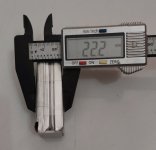
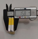
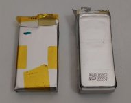
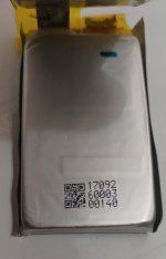
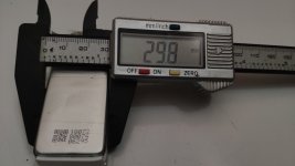
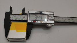
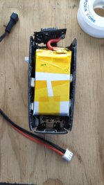
Some additional testing of the Anafi 2S2P 3100mAH Tattu battery pack.

BMS = Battery Management System. ~ (Tilde) = about or approximately.

Previous tests indicated that the BMS was auto-landing @ 1% and the voltage was still relatively high, (~7.5V) which should have had no influence. I’ve done this test a total of four times and the results have been <18 minutes @ hover. The battery pack had been charged each time using a USB C 65W PD charger as depicted in (Ref-011) at ~17W.

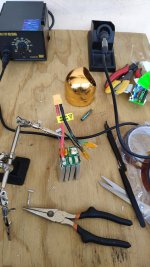
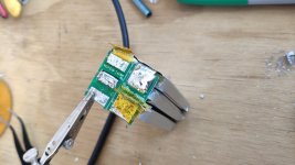
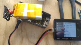
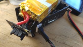
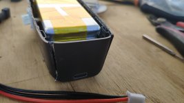
Wanting to charge the pack more quickly like the after-market triple charger does I robbed a connector, (Ref-007-009) to connect to the iCharger X6, (Ref-012) and balance charge using it. Let the fun begin!

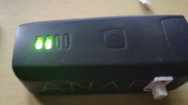
After charging with the X6 the auto-landing did not happen until ~ 23 minutes with the pack voltage @ 7.30V and each cell ~3.65V. The FF6 displayed 100% for ~ 6 minutes and then started to decline in value. This can be seen in the screen captures, (Ref-001-005). Ref-001 & 004 are USB charges, not X6 charges.

Ref-009.jpgRef-011.jpgRef-012.jpg

Observations/Comments: The BMS is still a mystery to me.

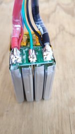
The three port after-market charger maximizes the charge rate the BMS will except, (2.7A or ~23.5W or 1C). Any charge current over 2.7A @ 8.7V the BMS will open the circuit stopping the charge. I have tested this aspect trying to charge the 3100mAH Tattu battery @ 1C. Damage to the Anafi battery pack is unlikely, but that is not to say the charger can’t have it’s own problems, (pictures & reviews on-line).

Some have mentioned installing a XT-60 connector & balance connector and charging with a typical LiPo HV charger. The problem with this is that the BMS doesn’t know the battery is fully charged. What happens is you can’t take off because the Anafi, FF6 & the BMS all see zero, (0) percent. How do I know, been there done that!

I could go on, but prefer to let others come to their own conclusions and question mine. Questions welcome and I’ll do my best to answer them in the thread.
 
Last edited:
This is a good thought. How's the battery been charged for those who have had this problem?

I have had two drops from the sky with 2 different Anafis (Thermal, Anafi). I only use the factory charger pack with the 5 USB to USB C cables.

Both batteries that where in the drones that fell had both had forced auto landings out of no where while using Pix4D Capture when they were both within 10- 20%.

Oddly the Thermal fell with the battery at around 70 - 80%.
 
  • Like
Reactions: Fox Fader
@Buck That is very useful data and I appreciate the time and effort that you have put into getting it.

Do you think that the reason that the BMS did not recognise the battery when you installed the XT-60 connectors and charged it external to the BMS was that the centre tap was not connected?

Do you have any way of telling whether the X6 charger is putting more charge into the battery than the BMS does via USB-C? The BMS may be charging the Constant Current part of the charge cycle and not fully completing the final Constant Voltage part that would put a bit more charge in the battery.

Can you ascertain whether the centre tap of the battery is available at any of the connections on the end of the battery case as this would be useful for determining the voltage of individual cells.
 
Last edited:
  • Like
Reactions: Gipsz Jakab
"Some have mentioned installing an XT-60 connector & balance connector and charging with a typical LiPo HV charger. The problem with this is that the BMS doesn't know the battery is fully charged. What happens is you can't take off because the Anafi, FF6 & the BMS all see zero, (0) percent. How do I know, been there done that! "

So how is it possible to charge with that 3-socket charger?
In the picture, you are also charging with an external charger via the drone connector.
If I think correctly, do you think that bypassing the BMS, the cells cannot be filled directly because then it will not take off due to 0%?
But it makes sense for someone to install a balance connector on the original battery, but the charging current has to go through the BMS.

You haven’t tested that if you plug it into an external charger after a normal USB charge, what does it show and compare that to when you charge with an external charger?
 
@Buck That is very useful data and I appreciate the time and effort that you have put into getting it.

Do you think that the reason that the BMS did not recognise the battery when you installed the XT-60 connectors and charged it external to the BMS was that the centre tap was not connected?

Do you have any way of telling whether the X6 charger is putting more charge into the battery than the BMS does via USB-C? The BMS may be charging the Constant Current part of the charge cycle and not fully completing the final Constant Voltage part that would put a bit more charge in the battery.

Can you ascertain whether the centre tap of the battery is available at any of the connections on the end of the battery case as this would be useful for determining the voltage of individual cells.
No the center tap was/is always connected using any charging method that includes balancing. This is accomplished by the BMS when using USB C charging or when charged using the after-market connection to the X6. (Ref-017 & 018)

Ref-017.jpg
Ref-018.jpg

When a battery is fully charged by any method @ 8.7V it doesn't matter how it was charged, it is fully charged. It only matters to the BMS, which apparently "must" see mA going in or out.

There does not appear to be any measure-able battery voltage at any of the 8 pins in the center of the Anafi connector. How nice that would be if there was!
 
  • Like
Reactions: edwardfcy1970
"Some have mentioned installing an XT-60 connector & balance connector and charging with a typical LiPo HV charger. The problem with this is that the BMS doesn't know the battery is fully charged. What happens is you can't take off because the Anafi, FF6 & the BMS all see zero, (0) percent. How do I know, been there done that! "

So how is it possible to charge with that 3-socket charger?
In the picture, you are also charging with an external charger via the drone connector.
If I think correctly, do you think that bypassing the BMS, the cells cannot be filled directly because then it will not take off due to 0%?
But it makes sense for someone to install a balance connector on the original battery, but the charging current has to go through the BMS.

You haven’t tested that if you plug it into an external charger after a normal USB charge, what does it show and compare that to when you charge with an external charger?
I believe he meant adding an XT60 connector on the battery board of the Anafi.
That way one would need only one Anafi battery board. One would be able to charge batteries externally and easily swap batteries of their choice.
We know that this method is not possible because the charge must flow through the battery board.
 
  • Like
Reactions: Gipsz Jakab
When a battery is fully charged by any method @ 8.7V it doesn't matter how it was charged, it is fully charged. It only matters to the BMS, which apparently "must" see mA going in or out.
I am afraid that I must disagree with that statement. Lithium based rechargeable batteries use a Constant Current/ Constant Voltage method of charging. During the constant current part the cell voltage will rise until it reaches 4.35v in the case of LiHv cells and then the battery charger will change to a constant voltage setting of 4.35v and the current into the battery will gradually reduce until it gets to zero when the charger will stop. The graph below is for a LiPo battery that is 4.2v fully charged but LiHv follow the same curve.
DwKfW.png
This indicates that when the battery reaches full voltage after about 100 minutes it is only at about 80% capacity. Most hobby battery chargers have a "Quick Charge" setting that only completes the Constant Current part of the charge which saves time if you are wanting to fly but at the expense of capacity.

On my other point @Gipsz Jakab is correct and my question is that if you attach an XT-60 connector to both the battery and the Anafi battery electronics you are then able to charge the battery outside of the case. If the battery is then connected to the case does the Anafi recognise that it is fully charged? In reading your previous posts it does not Therefore I was asking whether if the centre tap of the battery was also attached to the battery case whether the Anafi would then recognise a full battery as it needed to determine the cell voltages individually to be happy. Another forum member is experimenting with using Li-on 18650 cells that he is charging outside of the battery case and the Anafi recognises that the batteries are installed and their voltages. That led me to believe that the centre tap of the batteries needs to be connected.

I am sorry if that is a bit long winded, and it would be easier if we could talk face to face, but it is the nature of forums that misunderstandings are very easy.
 
This is the thread on @Bud UAV converting the battery pack to use 18650.

The second page has more videos from the member. I think that both @Gipsz Jakab and myself are envisaging having a similar modified battery pack but with replaceable LiHv batteries that can be charged using a normal hobby charger.
 
  • Like
Reactions: Gipsz Jakab
None of his videos indicate his charging method, but show a Anafi battery housing, (lower & upper). Sides and rear cut away, leaving the USB C charger mounted in the upper section as normal and the BMS attached to the lower/front section as normal. Maybe he'll have the answers your looking for.
 
Sorry if this was mentioned before, back on the Youtube page for the video that started all of this, Parrot did actually respond. It may be more of a PR response instead of a technical challenge, but at least we do know that they are lurking around Youtube and maybe possibly even around here. Maybe something comes of this, but that's wishful thinking on my part.
 
  • Like
Reactions: Fox Fader
This battery is almost what we would need
Voltage: 15.2V
Cell Count: 4S (4 Cells)
Capacity: 1350mAh
Discharge Rate: 100C
Charge Rate: 5C
Dimensions: 75 x 36 x 33mm (±4mm) (LxWxH)
Weight: 163g (±10g)


Anafi battery - 128g

Change config to 2700mAh 7.6V 2S2P
Shaving off that bulk should bring it closer to Anafi battery weight.
Based on the dimensions it may not be able to fit in the Anafi case.

I'd jump all over the batteries Solaris offered if it weren't for that exorbitant shipping fee to the US.
I did the swap on my worst Anafi battery today.
The cells are slightly wider which initially made it a tight fit with the side wall supports, and soft padding, of the Anafi battery case.
Cutting the rear corners caused less stress on the battery case, but cutting out the side supports(ground down to make the cuts smooth) and removing the soft padding made it fit almost perfectly.

I decided on using only 2 cells per battery which means I get 2 'healthy' Anafi batteries for less than US$30. It isn't an easy task, but maybe worth it.
 

Attachments

  • IMG_20210114_002158.jpg
    IMG_20210114_002158.jpg
    3.4 MB · Views: 11
  • IMG_20210114_002423.jpg
    IMG_20210114_002423.jpg
    1 MB · Views: 7
  • IMG_20210114_002539.jpg
    IMG_20210114_002539.jpg
    1.4 MB · Views: 7
  • IMG_20210114_001916.jpg
    IMG_20210114_001916.jpg
    454.7 KB · Views: 7
  • IMG_20210113_231845.jpg
    IMG_20210113_231845.jpg
    1.4 MB · Views: 7
  • IMG_20210113_231312.jpg
    IMG_20210113_231312.jpg
    3.9 MB · Views: 7
  • IMG_20210113_231522.jpg
    IMG_20210113_231522.jpg
    3.8 MB · Views: 8
  • IMG_20210113_120008.jpg
    IMG_20210113_120008.jpg
    840.6 KB · Views: 11
  • IMG_20210113_125114.jpg
    IMG_20210113_125114.jpg
    1.3 MB · Views: 11
  • IMG_20210113_132155.jpg
    IMG_20210113_132155.jpg
    3.8 MB · Views: 11
  • Like
Reactions: Gipsz Jakab
I did the swap on my worst Anafi battery today.
The cells are slightly wider which initially made it a tight fit with the side wall supports, and soft padding, of the Anafi battery case.
Cutting the rear corners caused less stress on the battery case, but cutting out the side supports(ground down to make the cuts smooth) and removing the soft padding made it fit almost perfectly.

I decided on using only 2 cells per battery which means I get 2 'healthy' Anafi batteries for less than US$30. It isn't an easy task, but maybe worth it.
Pity I cannot fly my newly swapped battery as yet, cause Anafi is still with Drone Nerds.
Here are some more progress photos and the almost finished product (need to seal the casing).

Weight before some hot glue and epoxy, 105.6g.
Onto the next one!
 

Attachments

  • IMG_20210113_160143.jpg
    IMG_20210113_160143.jpg
    4.5 MB · Views: 18
  • IMG_20210113_160155.jpg
    IMG_20210113_160155.jpg
    4 MB · Views: 17
  • IMG_20210113_162559.jpg
    IMG_20210113_162559.jpg
    1.1 MB · Views: 16
  • IMG_20210113_162619.jpg
    IMG_20210113_162619.jpg
    4 MB · Views: 16
  • IMG_20210113_163255.jpg
    IMG_20210113_163255.jpg
    3.4 MB · Views: 18
  • IMG_20210113_171032.jpg
    IMG_20210113_171032.jpg
    3.7 MB · Views: 17
  • IMG_20210113_174902.jpg
    IMG_20210113_174902.jpg
    4 MB · Views: 18
  • IMG_20210113_232942.jpg
    IMG_20210113_232942.jpg
    1.6 MB · Views: 17
Last edited:

Members online

Forum statistics

Threads
5,295
Messages
45,055
Members
7,965
Latest member
Peanut